Featured Project
LeafLink: Smart Plant Care System
Designed and built an IoT-enabled plant care system that monitored four environmental conditions, automatically dispensed water through a servo-actuated valve, and published real-time sensor data during a four-day deployment.
Overview
LeafLink is an automated plant care system designed to reduce manual watering while remotely monitoring the conditions surrounding an indoor plant. An ESP32 collected soil moisture, air temperature, relative humidity, and illuminance data, publishing each measurement to an MQTT-based IoT network at ten-second intervals.
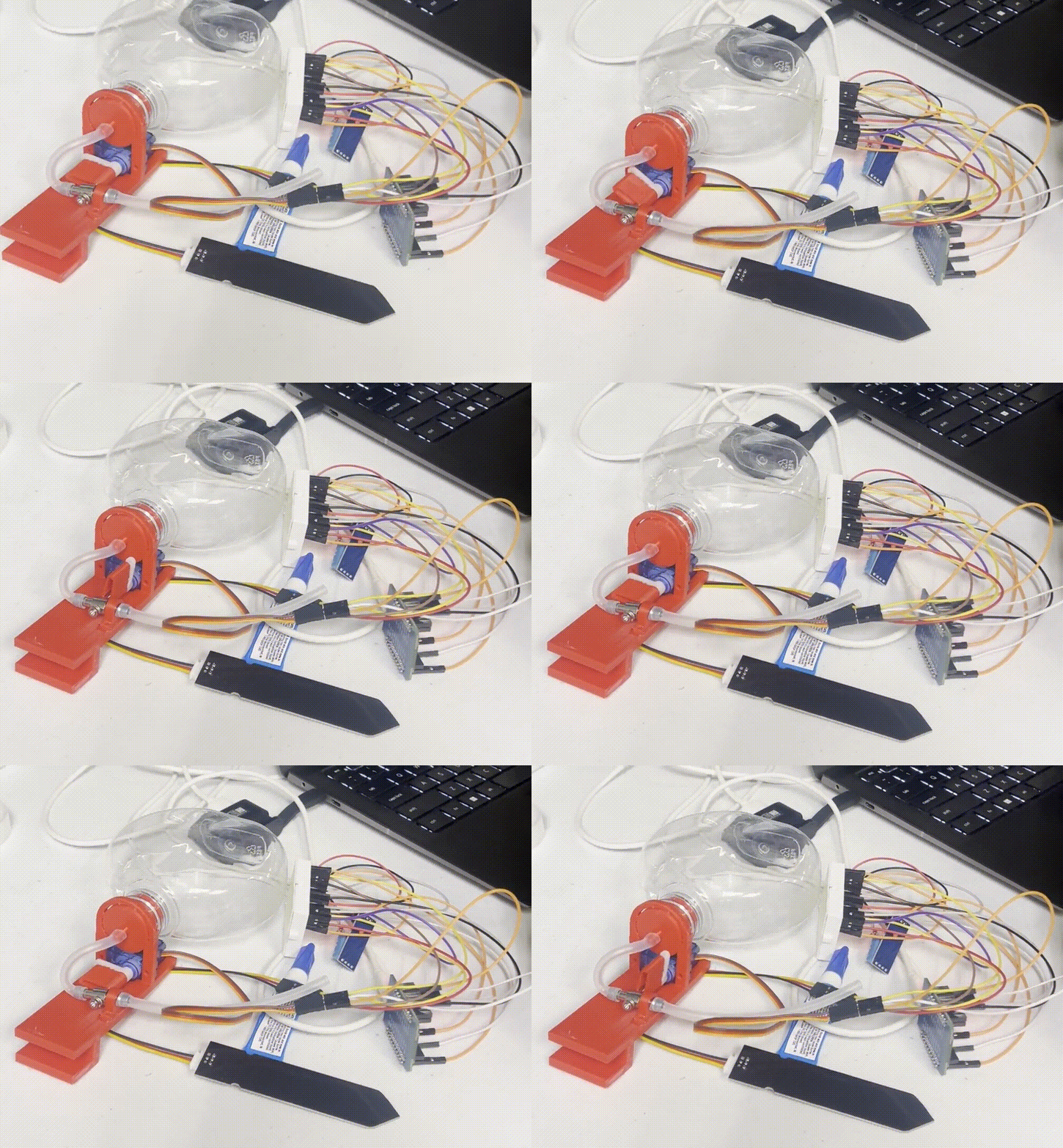
When the measured soil moisture fell below a calibrated threshold, the system actuated a mechanical valve to release water from an integrated reservoir. The electronics, valve, servo, water supply, and supporting structure were combined into a compact 3D-printed assembly that attached directly to the side of an existing plant pot rather than requiring a custom planter.
Key Results
4 Measurements
Soil moisture, air temperature, relative humidity, and illuminance
4-Day Deployment
Continuous environmental monitoring and automated watering
2 hr 16 min
Final single-print manufacturing time
10 Seconds
MQTT sensor-data publishing interval
My Contributions
- Led the mechanical design and product integration, developing the selected concept into the final SOLIDWORKS assembly, manufacturing drawings, and 3D-printed prototype.
- Designed a compact clamp-on structure that integrated the water reservoir, mechanical valve, servo motor, sensors, electronics, and wiring while separating water-handling components from the electrical system.
- Co-developed the ESP32 software for environmental sensing, threshold-based valve actuation, sensor conversion, and MQTT communication.
- Calibrated the valve actuation angles, debugged sensor and network communication issues, and completed the final four-day deployment and system validation.
Mechanical Design
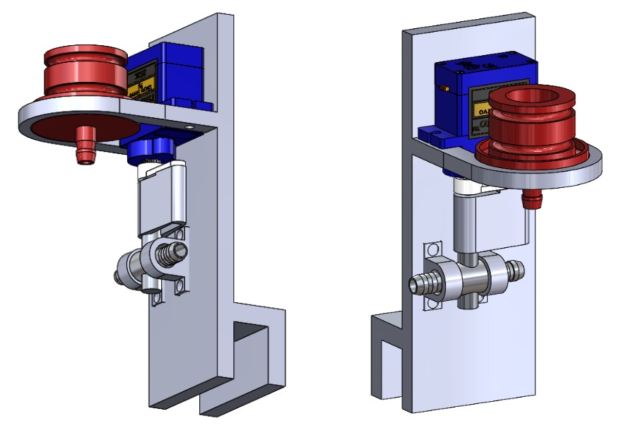
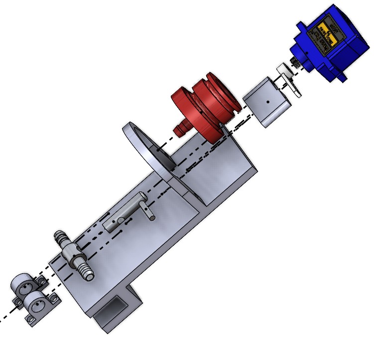
LeafLink was designed in SOLIDWORKS as a compact attachment that slid over the edge of an existing indoor plant pot. This approach avoided replacing the planter while creating an integrated support for the water reservoir, servo-actuated valve, sensors, electronics, and associated wiring.
The structure separated the water-handling components from the electronics by positioning the reservoir and valve toward the front while routing the control hardware and wiring behind them. The initial print revealed dimensional errors around the valve and lacked sufficient space for the water container, so the design was revised before the final 2-hour-16-minute print.
The final assembly fit the plant pot securely and provided reliable alignment between the servo and valve. To reduce the torque required from the small servo, the valve was partially disassembled and modified by removing its internal spring before final calibration.
Electronics and System Architecture
- ESP32 microcontroller for sensor acquisition, valve control, and IoT communication
- Capacitive soil-moisture sensor for determining when watering was required
- DHT11 sensor for air-temperature and relative-humidity monitoring
- Photocell and voltage-divider circuit for estimating illuminance
- Servo motor and modified mechanical valve for controlling water flow
- MQTT client for publishing environmental data to the Stevens IoT network
The system architecture centered on an ESP32 that sampled each environmental sensor, converted the raw measurements into usable values, evaluated the soil moisture against a watering threshold, and commanded the servo-actuated valve. Sensor readings were then transmitted to separate MQTT topics for remote monitoring and deployment analysis.
Component placement was arranged to reduce the risk of water reaching the breadboard and control electronics while keeping the wiring accessible for calibration and troubleshooting. Faulty connections and inconsistent photocell readings were resolved through component replacement and circuit rewiring during integration.
Software and Control Logic
The ESP32 sampled the soil-moisture sensor, DHT11, and photocell to determine soil moisture percentage, air temperature, relative humidity, and illuminance. Raw photocell voltage was converted into an estimated lux value, while the soil sensor was mapped between experimentally determined wet and dry calibration limits.
When soil moisture fell below 45%, the controller rotated the servo from its closed position at 0° to its calibrated open position at 100°. The valve remained open for two seconds before closing, allowing the system to dispense a controlled quantity of water rather than leaving the reservoir continuously open.
Each environmental measurement was published to the Stevens IoT network every ten seconds using MQTT. During the initial deployment, the sensors continued producing valid local readings but no data appeared online. Debugging identified a missing MQTT client-loop call, and restoring it enabled continuous publication throughout the final four-day deployment.